HCC2D
HCC2D Code Specification
Version 0.9.0 — Draft
Last updated: 5 July 2026
Origin and Publications
The HCC2D color barcode format originates from Marco Querini's Master's thesis in Computer Engineering (Laurea Specialistica in Ingegneria Informatica, A.A. 2009/2010), discussed on July 23, 2010, Analisi e progettazione di codici bidimensionali ad alta capacità. Sviluppo del lettore per gli ambienti desktop e mobile (Analysis and design of high-capacity two-dimensional codes. Development of the reader for desktop and mobile environments). During the thesis, a prototype was built for Android 1.6, in the very early stages of the Android operating system's rollout.
This specification is fully compatible with codes originally generated as described in the 2010 thesis, prior to the format being named HCC2D.
Conference publications related to this format appeared in September 2010 and September 2013 (respectively, “High capacity colored two dimensional codes” and “Color classifiers for 2D color barcodes”); the journal papers listed below are extended peer-reviewed versions of those conference papers.
The name "HCC2D" was introduced, and the format was subsequently described and its properties further analyzed, in the earlier conference publications and in the following peer-reviewed journal publications:
- Querini, M. and Italiano, G. F. (2014). Reliability and Data Density in High Capacity Color Barcodes. Special Issue of the Computer Science and Information Systems (ComSIS) Journal, 11(4), 1595–1615.
- Querini, M., Grillo, A., Lentini, A. and Italiano, G. F. (2011). 2D Color Barcodes for Mobile Phones. Special Issue of the International Journal of Computer Science & Applications (IJCSA), 8(1), 136–155.
This document is a standalone technical specification of the HCC2D format.
This specification may change before version 1.0.
License and Copyright
Copyright © 2010–2026 Marco Querini. All rights reserved.
This work is licensed under a Creative Commons Attribution-NoDerivatives 4.0 International License (CC BY-ND 4.0).
To view a copy of this license, visit: https://creativecommons.org/licenses/by-nd/4.0/
You are free to share, copy, and redistribute this specification document in any medium or format for any purpose, even commercially, provided that you give appropriate credit to the original author and do not distribute modified versions of the text. Implementing software, hardware, or systems that conform to the technical requirements defined in this specification is fully permitted and does not constitute a derivative work of this document.
This specification is openly published. Official HCC2D software implementations are distributed under separate proprietary terms.
This specification is provided "as is", without warranty of any kind. The author makes no representations or warranties regarding the accuracy, completeness, or fitness for any particular purpose of the information contained herein.
HCC2D™ is an unregistered trademark.
Introduction
HCC2D is a color two-dimensional barcode format. It reuses the square-matrix structure of QR Code while defining its own HCC2D-specific rules for color encoding, payload framing, symbol border semantics, version capacities, and codeword organization. In particular, HCC2D reuses finder-pattern, alignment-pattern, timing-pattern, format-information, version-information, mask formulas, and Reed-Solomon error-correction behavior that is compatible with QR Code / ISO/IEC 18004:2006, except where this specification explicitly defines different behavior.
QR Code is a registered trademark of DENSO WAVE INCORPORATED in Japan and in other countries. HCC2D is not sponsored, endorsed, or affiliated with DENSO WAVE INCORPORATED. The structural elements defined in QR Code / ISO/IEC 18004:2006 — including finder patterns, alignment patterns, timing patterns, format information, version information, and masking — are used herein as elements of a public technical standard. This document describes only the HCC2D-specific elements of the format and intentionally does not restate those elements.
HCC2D is not an alternative to QR Code but an extension of it. An HCC2D decoder shall also be a QR Code reader. In practical terms, an HCC2D decoder is fundamentally a standard QR Code decoder with additional functionality for recognizing and decoding colored modules. It uses the standard QR Code detection phase to detect the symbol structure. After detection and before payload decoding, the decoder determines whether to follow the standard QR Code decoding path, in which modules are interpreted as black-and-white modules, or the HCC2D decoding path, in which modules are interpreted as 4-color or 8-color modules. This choice is made by checking whether the HCC2D Color Palette Patterns are present on the perimeter of the symbol. If the Color Palette Patterns are not present, the decoder decodes the symbol as a standard QR Code. If the Color Palette Patterns are present, the decoder decodes the symbol as an HCC2D code according to the applicable HCC2D color rules. An HCC2D encoder produces symbols that share the same structural foundation as QR Code and shall be able to encode both QR Code symbols and HCC2D symbols.
This document specifies the HCC2D four-color and HCC2D eight-color code formats.
1. Scope
This document covers:
hcc2d4: 4-color HCC2Dhcc2d8: 8-color HCC2D
This specification defines:
- square symbols only
- versions
1..40 - error-correction levels
L,M,Q,H - byte-mode payload encoding only
This specification defines HCC2D payload framing using one BYTE segment.
1.1 Terms and Acronyms
- Color Palette Pattern: the outer border of an HCC2D code containing the cyclic sequence of palette colors, serving as a color legend
EC: error correctionEC level: error-correction levelECPB: error-correction codewords per blockMSB: most significant bitLSB: least significant bitRS: Reed-SolomonRGB: red, green, blueISO/IEC: International Organization for Standardization / International Electrotechnical Commission
Matrix terms:
module: one logical square cell of the symbolinner gridorinner matrix: the reused QR-compatible N×N matrix before the HCC2D border is addedfull symbol: the N+2 square produced after adding the HCC2D borderfunction module: a non-data module belonging to finder, alignment, timing, format, or version structuresdata module: a module whose state is determined by the encoded payload and error-correction bitstreamplane: one binary matrix extracted from the final interleaved bitstream
1.2 High-Level Structure
At a high level, HCC2D encoding proceeds as follows:
- frame the payload as one BYTE-mode segment
- choose the version and error-correction level
- generate data codewords, error-correction codewords, and the final interleaved bitstream
- split that final bitstream into two or three binary planes
- build one QR-compatible inner matrix per plane using one shared mask pattern
- combine plane bits into color indices for data modules
- render function modules in black and white
- add the HCC2D Color Palette Pattern border
HCC2D does not run a separate error-correction process per plane. One combined bitstream is produced first, and plane extraction happens only afterward.
2. Conformance Basis
A conforming implementation produces codes decodable by the official HCC2D Decoder, available on Google Play, Huawei AppGallery, and the App Store.
An implementation that claims conformance to this specification shall combine:
- an HCC2D-specific layer defined by this document; and
- a reused square-matrix coding layer whose behavior is compatible with QR Code / ISO/IEC 18004:2006 for all reused parts.
For interoperability with existing HCC2D decoders, the reused layer shall provide at least:
- Model-2-style square versions
1..40 - error-correction levels
L,M,Q,H - finder-pattern placement
- alignment-pattern placement from the coordinates listed in the HCC2D tables
- timing-pattern placement
- format-information generation and placement
- version-information generation and placement where applicable
- BYTE-mode data placement order in the inner matrix
- mask formulas for mask indices
0..7 - mask-penalty evaluation compatible with QR Code / ISO/IEC 18004:2006, except for the HCC2D-specific rule using the inverted plane 0 only in section 10
- Reed-Solomon parity generation and codeword interleaving compatible with QR Code / ISO/IEC 18004:2006, except for the HCC2D-specific total codeword counts and block multiplicities defined in sections 20 and 21
Therefore:
- this specification is not fully standalone
- an implementation that already has those reused QR Code / ISO/IEC 18004:2006-compatible behaviors can implement interoperable HCC2D symbol generation from this specification
- an implementation that has this specification together with the QR Code specification for the reused parts has the information needed to implement interoperable HCC2D symbol generation
In practical terms, HCC2D is not a replacement for QR-style square-matrix construction. It is a color-capacity and framing layer built on top of a reused QR-compatible inner symbol. Therefore the normative HCC2D differences are concentrated in:
- payload framing
- total codeword capacities and block multiplicities
- bit-plane extraction and color interpretation
- input selection for the data masking algorithm: inverted plane 0 only
- function-module rendering rule
- HCC2D outer border semantics
A format or symbol may be referred to as HCC2D only if it conforms to this specification. Use of the name HCC2D to describe a non-conformant format or symbol is misleading and not sanctioned by this specification.
3. Encoding Parameters
A conforming HCC2D symbol-generation process is parameterized by at least these logical values:
payload: required, non-empty byte arraymode:hcc2d4orhcc2d8ec_level: one ofL,M,Q,Hversion:0means auto-select; otherwise1..40scale: pixels per module for raster rendering, if raster output is producedquiet_zone: modules of white margin around the rendered symbol, if raster output is producedpalette_rgb: optional RGB override
The first four parameters affect the logical HCC2D symbol. The last three affect visual rendering only.
Default values, user-interface behavior, and command-line conventions are outside the scope of this specification.
Additional parameter notes:
payloadis interpreted strictly as raw bytes- this specification does not define text transcoding, multi-segment optimization, numeric mode, or alphanumeric mode
modedetermines the number of planes and the palette familyec_levelselects the normative table row within the chosen versionversioncontrols capacity, inner dimension, alignment coordinates, and block structurescale,quiet_zone, andpalette_rgbdo not change the encoded logical bitstream
4. Symbol Geometry
For both HCC2D modes, version v uses an inner square grid of dimension:
N = 17 + 4*v
Examples:
- version 1 →
21 × 21 - version 10 →
57 × 57 - version 40 →
177 × 177
The inner grid reuses finder-pattern, alignment-pattern, timing-pattern, format-information, and version-information structures that follow QR Code / ISO/IEC 18004:2006-compatible rules.
HCC2D then adds its own one-module outer border on all four sides:
- inner dimension =
N - full dimension =
N + 2
This HCC2D-specific outer border is the Color Palette Pattern.
The distinction between inner grid and full symbol is normative:
- all reused QR-compatible placement logic operates on the inner
N × Nmatrix - the HCC2D Color Palette Pattern sits outside that inner matrix
- rendering and raster output use the full
N + 2dimension
Therefore, whenever this document refers to function patterns, data placement, masking, or version geometry, those rules apply first to the inner matrix, and only afterward is the HCC2D border added.
5. Color Indices and Default Palettes
This section defines the color index bit layout for HCC2D4 and HCC2D8, the two standard Color Palette Models (Model 1 for screen display and Model 2 for print), the classification of palette models, and the rules for palette customization.
5.1 HCC2D4 — Color Palette Model 1 — Definition
HCC2D4 codes with Color Palette Model 1 shall use the following colors for palette indices 0..3. Luminance is approximate, computed as Y = 0.299R + 0.587G + 0.114B.
| Index | Color | RGB | Luminance (Y) |
|---|---|---|---|
0 | black | RGB(0, 0, 0) | ≈ 0 |
1 | red | RGB(220, 0, 0) | ≈ 66 |
2 | cyan | RGB(0, 200, 220) | ≈ 142 |
3 | white | RGB(255, 255, 255) | ≈ 255 |
Color index bit layout:
- bit 1 = MSB plane
- bit 0 = LSB plane
Therefore:
00 → 0 → black01 → 1 → red10 → 2 → cyan11 → 3 → white
The ordering is logical, not merely visual. Index 0 is the dark anchor and index 3 is the white anchor of the four-color family.
5.2 HCC2D8 — Color Palette Model 1 — Definition
HCC2D8 codes with Color Palette Model 1 shall use the following colors for palette indices 0..7. Luminance is approximate, computed as Y = 0.299R + 0.587G + 0.114B.
| Index | Color | RGB | Luminance (Y) |
|---|---|---|---|
0 | black | RGB(0, 0, 0) | ≈ 0 |
1 | dark red | RGB(200, 0, 0) | ≈ 60 |
2 | dark green | RGB(0, 130, 0) | ≈ 76 |
3 | dark navy | RGB(0, 60, 180) | ≈ 56 |
4 | light cyan | RGB(0, 215, 235) | ≈ 153 |
5 | light yellow | RGB(255, 220, 50) | ≈ 211 |
6 | light magenta | RGB(255, 130, 230) | ≈ 179 |
7 | white | RGB(255, 255, 255) | ≈ 255 |
Color index bit layout:
- bit 2 = plane 0 / MSB plane
- bit 1 = plane 1
- bit 0 = plane 2 / LSB plane
Therefore the color index equals the 3-bit value formed from the three plane bits.
Again, the ordering is logical. Index 0 is the dark anchor and index 7 is the white anchor of the eight-color family.
5.3 Color Palette Model 1 — Design Rationale
The RGB values of Color Palette Model 1 (defined in sections 5.1 and 5.2) were deliberately chosen to avoid the extremes of the sRGB gamut, where different display profiles and hardware color gamuts diverge most. The decoder samples the Color Palette Pattern at runtime on the actual display screen — which may be sRGB, wide-gamut, AMOLED, or LCD, and is almost certainly uncalibrated. Near-boundary channel values (close to 0 or 255) are rendered differently across display types; by capping active channels at 200–220 rather than 255, the palette colors land in the interior of the sRGB gamut where different screens agree more reliably on the perceived color. This reduces cross-display color drift and improves the stability of color sampling during decoding.
This RGB capping choice also produces a luminance distribution consistent with the ordering requirement of section 5.9. For HCC2D8 (section 5.2), indices 0–3 (black, dark red, dark green, dark navy) all fall below the luminance midpoint (Y < 128), while indices 4–7 (light cyan, light yellow, light magenta, white) all fall above it (Y > 128). The gap between index 3 (dark navy, Y ≈ 56) and index 4 (light cyan, Y ≈ 153) is approximately 97 luminance units.
Color Palette Model 1 is the screen-validated baseline. It makes no claim to being optimal for print.
5.4 HCC2D4 — Color Palette Model 2 — Definition
For HCC2D4, all intermediate colors are single-ink. Yellow is excluded because it provides insufficient contrast with white paper:
| Index | Color | RGB | Ink Channels | Luminance (Y) |
|---|---|---|---|---|
0 | black | RGB(0, 0, 0) | K | ≈ 0 |
1 | magenta | RGB(255, 0, 255) | M | ≈ 105 |
2 | cyan | RGB(0, 255, 255) | C | ≈ 179 |
3 | white | RGB(255, 255, 255) | no ink (paper) | ≈ 255 |
5.5 HCC2D8 — Color Palette Model 2 — Definition
For HCC2D8, the palette exhausts all three single-ink CMYK primaries and their three binary full-saturation combinations. No three-ink combination is used:
| Index | Color | RGB | Ink Channels | Luminance (Y) |
|---|---|---|---|---|
0 | black | RGB(0, 0, 0) | K | ≈ 0 |
1 | blue | RGB(0, 0, 255) | C + M (100%) | ≈ 29 |
2 | red | RGB(255, 0, 0) | M + Y (100%) | ≈ 76 |
3 | magenta | RGB(255, 0, 255) | M | ≈ 105 |
4 | green | RGB(0, 255, 0) | C + Y (100%) | ≈ 150 |
5 | cyan | RGB(0, 255, 255) | C | ≈ 179 |
6 | yellow | RGB(255, 255, 0) | Y | ≈ 226 |
7 | white | RGB(255, 255, 255) | no ink (paper) | ≈ 255 |
5.6 Color Palette Model 2 — Design Rationale
Color Palette Model 2 is the print-optimized palette, defined for both HCC2D4 and HCC2D8. For print, the problem differs from screens: ink gamut, paper white point, and lighting conditions during scanning introduce different sources of variability. Color Palette Model 2 is built on the principle of minimizing the number of ink channels per module color. Single-ink colors are maximally stable across printers; each additional ink channel introduces dot gain interactions that vary with printer, paper, and ink density.
Both Color Palette Model 2 palettes satisfy the dark/light ordering of section 5.9. For HCC2D8, the split is particularly clear: indices 0–3 (black, blue, red, magenta) all fall below the luminance midpoint (Y < 128), while indices 4–7 (green, cyan, yellow, white) all fall above it (Y > 128), with a gap of approximately 45 luminance units between index 3 (magenta, Y ≈ 105) and index 4 (green, Y ≈ 150).
5.7 Color Palette Model Classification
HCC2D codes are classified by their color palette as follows. The model number is a property of the palette, not of the code format; the decoder is palette-agnostic.
- Color Palette Model 1: codes that use the exact default palette defined in sections 5.1 and 5.2. This is the standard, fully interoperable palette. Color Palette Model 1 has been validated to work well when codes are displayed on screens (computer monitors, smartphones, and similar devices). Any implementation that claims HCC2D conformance without further qualification implies Color Palette Model 1.
- Color Palette Model 2: codes that use the print-optimized palette defined in sections 5.4 and 5.5, covering both HCC2D4 and HCC2D8. Designed for print-and-scan workflows.
- Invalid palette: a palette that does not have black at index 0 or white at the last index. Codes using such a palette are not valid HCC2D codes. Conforming encoders shall reject such configurations (see section 5.8).
- Non-standard / experimental palette: a palette that keeps black at index 0 and white at the last index but uses different intermediate colors. Codes produced with such a palette may or may not be decodable, depending on how chromatically distinct the chosen colors are. The encoding implementation bears sole responsibility for any codes that fail to decode.
Color palette model numbers are assigned exclusively by this specification. Additional color palette models (Color Palette Model 3 and so on) may be defined in future versions of this specification as other color combinations are experimentally validated to perform well in specific use cases, such as computer-to-phone scanning or phone-to-phone scanning.
Palette modifications should be limited to experimental use. For production use, Color Palette Model 1 should be used when codes are to be displayed on screens (computer monitors, smartphones, and similar devices); Color Palette Model 2 should be used when codes are to be printed.
Implementations that produce codes with a non-standard palette shall explicitly disclose this to their users, stating that the codes use a non-standard palette and may not be decodable by all HCC2D decoders.
5.8 Palette Override
The first palette entry and the last palette entry are normative anchors and shall not be changed:
- for
hcc2d4, index0shall remain black and index3shall remain white - for
hcc2d8, index0shall remain black and index7shall remain white
Therefore:
- in
hcc2d4, only indices1and2may be customized - in
hcc2d8, only indices1through6may be customized
When a palette override is provided:
- 4-color mode requires exactly
12bytes (4 * 3) - 8-color mode requires exactly
24bytes (8 * 3) - the byte layout is still the full palette in palette-index order, then RGB component order
- however, conforming encoders shall reject overrides whose first entry is not black or whose last entry is not white
Byte order is palette-entry order, then RGB component order:
- HCC2D4:
R0 G0 B0 R1 G1 B1 R2 G2 B2 R3 G3 B3 - HCC2D8:
R0 G0 B0 ... R7 G7 B7
Normative anchor values:
hcc2d4:R0 G0 B0 = 0 0 0andR3 G3 B3 = 255 255 255hcc2d8:R0 G0 B0 = 0 0 0andR7 G7 B7 = 255 255 255
The symbol logic uses indices only. Custom RGB values do not affect codewords, bitstream construction, version selection, mask selection, or matrix layout, but they do affect rendered appearance.
Equivalently, HCC2D first determines a logical color index for each module and only then maps that index to an RGB triple for rendering.
5.9 Recommended Luminance Ordering for Customized Palettes
This subsection is advisory.
When a customized palette is used, implementations should preserve a darker lower half and a lighter upper half. This recommendation is motivated by the HCC2D mask-selection rule defined later in this specification.
HCC2D mask selection is not performed on the final full-color rendered symbol. Instead, mask selection is performed on a binary proxy derived from one bit-plane only:
- only plane
0participates in mask selection - for
hcc2d4, plane0is the color most-significant bit - for
hcc2d8, plane0is the color most-significant bit (bit2) - that one plane is extracted from the final interleaved bitstream
- that plane is then inverted
- the reused QR-compatible mask penalty rules are evaluated on that inverted single-plane proxy
Therefore, only one bit per module directly influences mask choice.
This has an important practical consequence. The mask is chosen using QR-style binary penalty rules, but the final HCC2D symbol is a multi-color symbol. For the QR-style mask-selection process to remain meaningful for HCC2D, the binary proxy used for mask choice should still correlate reasonably well with the apparent darkness structure of the final rendered symbol.
That correlation is improved when lower palette indices are darker and higher palette indices are lighter. In that arrangement, the single plane used for mask selection still acts as a useful coarse approximation of how dark-versus-light regions are distributed in the final HCC2D symbol.
Therefore, palette customization should preserve a rendered luminance ordering in which the lower half is darker overall and the upper half is lighter overall, consistent with the logical significance ordering of the color indices.
In practical terms:
- lower palette indices should correspond to darker colors
- higher palette indices should correspond to lighter colors
- the first entry shall remain black
- the last entry shall remain white
Recommended ordering for hcc2d4:
- index
0shall be black - index
1should be visually darker than index2 - index
3shall be white - as a 4-color family-level guideline, indices
0and1should form the darker half of the palette and indices2and3should form the lighter half
Recommended ordering for hcc2d8:
- index
0shall be black - index
7shall be white - indices
1,2, and3should fall in the darker half of the palette - indices
4,5, and6should fall in the lighter half of the palette - as an 8-color family-level guideline, indices
0through3should be darker overall than indices4through7
This recommendation does not change symbol logic, because HCC2D uses palette indices rather than luminance values when constructing the symbol. A palette that violates the recommended darker-lower / lighter-upper balance may still produce decodable symbols. However, doing so weakens the intended relationship between:
- the proxy used during mask selection
- the apparent darkness distribution of the final rendered symbol
- the visual stability of the customized palette across different scanning conditions
If that dark-versus-light balance is preserved, the reused QR-style mask rules remain a reasonable and useful heuristic for HCC2D as well.
If that balance is not preserved:
- the encoder may still generate valid symbols
- decoders may still successfully decode those symbols
- but the selected mask is then optimized for the binary QR-style proxy rather than for a final color arrangement whose perceived darkness follows the same structure
In that case, mask selection still works in the narrow sense that a mask is chosen and the resulting symbol may remain decodable, but the QR-style penalty model becomes less representative of the visual properties of the actual HCC2D symbol.
For that reason, a customized palette should preserve darker colors in the lower indices and lighter colors in the higher indices.
6. Payload Framing
HCC2D payload framing uses one BYTE segment.
- segment marker bits:
0100 - count field width:
16bits in both HCC2D modes, for all versions - count value: payload length in bytes
- payload bytes: appended verbatim,
8bits each, most-significant bit first
The logical payload bitstream before termination is:
0100 || byte_count_16 || payload_bytes
Termination bits, byte alignment, pad bytes, Reed-Solomon parity generation, and final interleaving follow QR Code / ISO/IEC 18004:2006-compatible rules, except where this specification explicitly defines HCC2D-specific behavior.
Important consequences of this framing rule:
- the count field is always sixteen bits for HCC2D, regardless of version
- the count value is a byte count, not a bit count and not a character count
- the payload bytes are appended verbatim in most-significant-bit-first order
- this specification defines exactly one BYTE segment per HCC2D symbol
7. Version Selection
If a version is explicitly specified, it shall be used only if the payload fits.
If automatic version selection is used, the smallest fitting version shall be selected.
For a given HCC2D mode, version, and error-correction level:
total_codewords,data_codewords,ec_codewords, and block layout are given by the explicit HCC2D tables in sections 20 and 21- a payload fits iff its framed bitstream can be terminated and padded into exactly
data_codewordsbytes
For this purpose, the framed bitstream length before termination is:
4 + 16 + 8 * payload_length
where 4 is the BYTE mode indicator and 16 is the HCC2D byte-count field width.
A payload fits when that framed bitstream can be:
- optionally terminated by up to four zero bits
- padded with zero bits to the next byte boundary
- padded with alternating pad bytes until the exact data-codeword capacity is reached
without exceeding the available data-codeword count for the selected mode, version, and error-correction level.
8. HCC2D Codeword Organization
The HCC2D parameter tables in sections 20 and 21 are normative.
Error-correction structure follows ISO/IEC 18004:2006-compatible rules, except where this specification explicitly defines HCC2D-specific behavior.
Each table row gives:
dim: inner dimensionalign: alignment-pattern center coordinatestotal: total codewordsdata: data codewordsec: error-correction codewordsecpb: error-correction codewords per blockblocks: block multiplicities and data codewords per block
Those values fully determine the HCC2D codeword organization for each version and level.
For hcc2d4, the total codeword count for each version and level is exactly twice the corresponding reused QR Code / ISO/IEC 18004:2006-compatible base structure.
For hcc2d8, the total codeword count for each version and level is exactly three times the corresponding reused QR Code / ISO/IEC 18004:2006-compatible base structure.
More precisely:
hcc2d4keeps the reused QR Code / ISO/IEC 18004:2006-compatible codewords-per-block values and doubles the block multiplicitieshcc2d8keeps the reused QR Code / ISO/IEC 18004:2006-compatible codewords-per-block values and triples the block multiplicities
This is the mechanism by which HCC2D increases total bit capacity while continuing to use reused QR-compatible Reed-Solomon procedures.
9. Plane Construction
Let the final interleaved codeword bitstream be B.
Plane construction is performed only after:
- data codewords have been formed
- error-correction codewords have been generated
- final interleaving has been completed
HCC2D does not create separate error-correction streams per plane. Instead, one combined final bitstream is produced first and then split by stride into planes.
9.1 HCC2D4 — Two planes
hcc2d4 uses two planes.
Plane extraction is by bit deinterleaving from the final bitstream:
- plane 0 takes bits at positions
0, 2, 4, ... - plane 1 takes bits at positions
1, 3, 5, ...
Plane 0 is the MSB plane. Plane 1 is the LSB plane.
Data module color index:
color = (plane0_bit << 1) | plane1_bit
Equivalently, if the final interleaved bitstream is B[0], B[1], B[2], ..., then symbol module colors are driven by bit pairs:
(B[0], B[1]), (B[2], B[3]), (B[4], B[5]), ...
9.2 HCC2D8 — Three planes
hcc2d8 uses three planes.
Plane extraction is:
- plane 0 takes bits at positions
0, 3, 6, ... - plane 1 takes bits at positions
1, 4, 7, ... - plane 2 takes bits at positions
2, 5, 8, ...
Plane 0 is the MSB plane. Plane 2 is the LSB plane.
Data module color index:
color = (plane0_bit << 2) | (plane1_bit << 1) | plane2_bit
Equivalently, if the final interleaved bitstream is B[0], B[1], B[2], ..., then symbol module colors are driven by bit triples:
(B[0], B[1], B[2]), (B[3], B[4], B[5]), (B[6], B[7], B[8]), ...
The plane order is normative and shall not be permuted. In hcc2d4, plane 0 is the most-significant bit and plane 1 is the least-significant bit. In hcc2d8, plane 0 is bit 2, plane 1 is bit 1, and plane 2 is bit 0.
10. Mask Selection
A single mask pattern in 0..7 shall be used for all planes of a symbol.
Mask selection follows ISO/IEC 18004:2006-compatible rules, except where this specification explicitly defines HCC2D-specific behavior.
HCC2D-specific behavior for candidate evaluation:
- build a proxy bitstream from plane 0 only
- invert every bit of that plane-0 stream
- use that inverted stream for mask-penalty evaluation
Mask selection procedure:
- for each candidate mask index in
0..7, apply that mask to the inverted plane-0 bitstream and build a candidate inner matrix from it - compute the mask penalty on that candidate matrix
- select the mask index with minimum penalty
Tie-breaking is by first minimum encountered, i.e. lowest mask index.
Once the winning mask index is chosen, that one index shall be reused for every plane of the symbol. HCC2D does not choose different mask patterns for different planes.
11. Inner-Matrix Construction
Each plane is converted into an inner matrix using the chosen version and the chosen common mask pattern.
Important: all planes use the same function pattern geometry, the same version, the same format bits, and the same mask index. They differ only in data bits.
This document does not restate the reused finder-pattern, alignment-pattern, timing-pattern, format-information, version-information, Reed-Solomon, or mask formulas in full.
Thus, inner-matrix construction for HCC2D can be understood as repeated QR-compatible matrix construction over the same geometry, once per plane, with only the plane bitstream changing from one pass to the next.
12. Function Module Coloring
For hcc2d4 and hcc2d8, data modules use the multi-plane color mapping described above, but function modules are rendered only in black and white:
- if plane 0 at that function-module coordinate is
1, render black - otherwise render white
In practice this is safe because function modules are identical across all planes.
This rule applies to all reused structural modules in the inner matrix, including finder patterns, alignment patterns, timing patterns, format information, and version information where applicable.
13. Color Palette Pattern
The Color Palette Pattern shall be implemented exactly as specified: decoders sample its modules to reconstruct the color palette. A decoder has no prior knowledge of the palette colors, except that the first entry is black and the last is white. The Color Palette Pattern is therefore necessary for decoding.
Let the inner dimension be N.
The HCC2D border sits one module outside the inner grid:
- top border row is at logical row
-1 - bottom border row is at logical row
N - left border column is at logical column
-1 - right border column is at logical column
N
The HCC2D code shifts those logical coordinates by +1 in both axes, producing a (N+2) × (N+2) grid.
The Color Palette Pattern is a structural part of HCC2D, not optional ornamentation. Its geometry and color-index order are part of the format definition.
13.1 Color Palette Pattern period
hcc2d4: periodP = 4hcc2d8: periodP = 8
The active spans on each edge cycle through all P palette indices repeatedly. The exact formula for each edge, including the starting index and cycling direction, is given in section 13.2.
The cycle is defined in terms of logical palette indices, not literal RGB values.
13.2 Exact Color Palette Pattern color formulas
Let row and col be logical coordinates in the border coordinate system described above.
The Color Palette Pattern border shall use these exact rules:
- Top edge: if
row == -1and8 ≤ col < N - 8, thencolor = (col - 8) mod P - Bottom edge: if
row == Nand8 ≤ col < N, thencolor = (col - 8) mod P - Left edge: if
col == -1, letstart = N - 9. If8 ≤ row ≤ start, thencolor = (start - row) mod P - Right edge: if
col == Nand8 ≤ row < N, thencolor = (row - 8) mod P - All remaining border cells:
color = P - 1
This means the non-cycling border cells, including corners and excluded spans near the finder patterns, are always the highest palette index:
3for HCC2D4 → white7for HCC2D8 → white
13.3 Color Palette Pattern replicas by mode
Not all border modules carry palette colors. Modules at the corners and near the finder patterns are fixed white (color = P − 1, as defined in section 13.2). The length of the segment that cyclically replicates the palette colors on each edge is:
- top edge:
N − 16modules - bottom edge:
N − 8modules - left edge:
N − 16modules - right edge:
N − 8modules
For HCC2D8 (P = 8), the same lengths apply.
The exact sequence per edge — including starting index and direction — is determined by the formulas in section 13.2. The top, bottom, and right edges increment with their scan coordinate. On the left edge the palette index decreases with increasing row; the exact starting index at each version is given by the formula in section 13.2.
13.4 Decoder-facing interpretation
The decoder samples these strips to recover palette statistics. Therefore the border is part of the symbol format, not merely a decoration.
Any implementation that changes the span geometry, cycling direction, or fallback white cells of the Color Palette Pattern would generate a non-conformant symbol.
14. Rendered Output Coordinates
This section defines raster rendering of a logical HCC2D symbol. The logical symbol is fully defined without fixing any particular pixel size.
14.1 Module coordinates
For HCC2D modes:
- full module grid size =
N + 2 - inner module
(x, y)maps to rendered module(x + 1, y + 1)
14.2 Quiet zone
The rasterized image adds quiet_zone modules of background color on all four sides.
Background color index:
- HCC2D4:
3(white) - HCC2D8:
7(white)
14.3 Image size in pixels
Let F be the full module dimension:
F = N + 2
Then:
- image width =
(F + 2 * quiet_zone) * scale - image height = same
Each logical module is rasterized as a scale × scale solid-color square.
For HCC2D symbols, the quiet zone uses the highest palette index:
3forhcc2d47forhcc2d8
Under the default palettes, this corresponds to white.
15. Decoder-Relevant Structural Rules
15.1 HCC2D count field
The BYTE count field is 16 bits in both HCC2D modes.
15.2 Plane order
For 4-color HCC2D:
- plane 0 is the color MSB
- plane 1 is the color LSB
For 8-color HCC2D:
- plane 0 is the color MSB (bit 2)
- plane 1 is bit 1
- plane 2 is the color LSB (bit 0)
15.3 Common mask
All planes shall use the same mask pattern.
These rules are decoder-relevant because a decoder that assumes QR-style variable BYTE count-field widths, a different plane significance order, or independent per-plane masks would not correctly interpret a conforming HCC2D symbol.
16. Encoding Procedure
A conforming HCC2D encoding procedure shall perform the following steps:
- Validate inputs.
- Select symbol family (
hcc2d4orhcc2d8). - Select error-correction level (
L/M/Q/H). - Choose version: use the explicitly specified version if it fits; otherwise, when automatic selection is used, choose the smallest fitting version.
- Build logical payload bitstream:
0100 || byte_count_16 || payload_bytes - Determine family-specific capacity and block layout from the explicit HCC2D table for the chosen mode, version, and level.
- Apply termination and pad bytes.
- Generate parity and interleave codewords using the reused error-correction structure.
- Split the final bitstream into 2 or 3 planes by strided extraction.
- Select one common mask index: for HCC2D modes, evaluate penalties using inverted plane 0 only.
- Build one inner matrix per plane using the common version, EC level, and mask.
- Render data modules:
- HCC2D4: color index from 2 plane bits
- HCC2D8: color index from 3 plane bits
- Render function modules as black/white from plane 0.
- Add the exact one-module Color Palette Pattern border using the coordinate formulas in section 13.
- Add white quiet zone.
- Rasterize modules into pixels if a raster image output is needed.
The order of operations matters. In particular:
- error correction and interleaving occur before plane extraction
- mask selection occurs once and is shared by all planes
- inner-matrix construction occurs before the Color Palette Pattern border is added
- the quiet zone is outside the full HCC2D symbol and is not part of the logical payload structure
17. HCC2DF Payload Wrapper
This section does not define the HCC2D code itself.
It defines an optional payload-wrapper format, HCC2DF, that may be used before HCC2D symbol encoding when the application wants to carry a filename together with file content. When used, the HCC2DF byte stream becomes the payload defined in sections 3, 6, and 16 of this specification.
HCC2DF is an application-level wrapper layered on top of HCC2D payload bytes. It is not part of the HCC2D symbol geometry or color logic.
17.1 HCC2DF byte layout
The HCC2DF payload bytes are:
- ASCII magic:
"HCC2DF"→ 6 bytes - wrapper version byte:
0x01 - compression flag byte:
0x00= raw content0x01= zlib-compressed content
- filename length: 1 byte
- filename bytes: UTF-8, exactly
filename_lengthbytes - content bytes: raw file bytes or compressed file bytes
No checksum field, footer, or nested metadata structure is defined by this wrapper.
17.2 Filename constraints
- filename shall be non-empty
- filename shall be at most
127UTF-8 bytes - filename shall not contain
/ - filename shall not contain
\
17.3 Compression rule
If compression is attempted, the content is compressed using zlib compress2(..., Z_DEFAULT_COMPRESSION).
Compression should be used only if all of the following are true:
- compression succeeds
- original file size is at least
128bytes - compressed size is strictly less than
90%of original size
Otherwise raw file bytes should be stored and the compression flag should be 0x00.
The 128-byte minimum reflects the fixed overhead that zlib compression always introduces. The zlib wrapper alone adds 6 bytes (2-byte header + 4-byte Adler-32 checksum). On top of that, deflate block headers add further overhead: a stored block adds 5 bytes, and a dynamic Huffman block adds the code table description, which can be 20–50 bytes for small inputs — giving a realistic total overhead of around 36 bytes. To see why 128 bytes is the right threshold, consider the two cases:
- 64-byte input: budget to pass 90% rule = 64 × 0.9 − 36 = 21.6 bytes left for actual data — the content would need to compress to ~34%, achievable only for highly repetitive sequences.
- 128-byte input: budget = 128 × 0.9 − 36 = 79 bytes left for actual data — the content would need to compress to ~62%, which is realistic for typical text, JSON, or URLs.
Below 128 bytes the overhead consumes so much of the available budget that compression is unlikely to produce a meaningful result for any real-world payload.
This rule prefers compression only when it gives a clear size benefit. Implementations may use a different threshold (e.g. 95%) but this is not recommended: a higher threshold means compressing data that saves only a few percent of space, which is not a meaningful benefit — storing the raw bytes is simpler and the result may be practically almost the same size. In any case, implementations that deviate from this recommendation will still produce codes decodable by the official HCC2D Decoder, as long as the compression flag and the content remain coherent: if the flag is 0x01, the content shall be valid zlib-compressed data; if the flag is 0x00, the content shall be the raw bytes.
17.4 Scope relationship to HCC2D
HCC2DF is an optional wrapper carried inside HCC2D payload bytes. It is not part of the HCC2D code structure, color encoding, codeword organization, or symbol geometry.
18. HCC2DST Streaming Transfer Protocol
HCC2DST is an application-level protocol for transferring a single file across multiple HCC2D symbols. Each symbol carries one Reed-Solomon-coded shard of the file, wrapped in an HCC2DF container (§17). HCC2DST is optional and does not affect code structure, color encoding, codeword organization, or symbol geometry.
Full technical details of this protocol will be described in a future version of this specification.
19. Implementation Recommendations
The following are advisory recommendations for implementors. They are not normative requirements of this specification. Throughout this specification, normative requirements are expressed using "shall" and "shall not", advisory recommendations using "should" and "should not", and permitted options using "may".
Recommended error-correction level: For HCC2D codes, levels Q or M should be used. Level L should not be used for general use. Level H provides maximum robustness at the cost of significantly reduced payload capacity.
Recommended mode: For production use, hcc2d4 should be used. hcc2d8 offers greater payload capacity but requires more chromatically consistent display and scanning conditions.
Print and production quality: For printed production-use codes:
- A lossless output format (PNG, SVG, or PDF) should be used. Lossy formats such as JPEG introduce compression artifacts that corrupt module colors.
- Each module should be rendered as a solid color block; halftoning should not be used.
- The aspect ratio should not be stretched, squeezed, or distorted.
- Blur, antialiasing, and resampling should not be applied after rasterization.
- The module size should be at least 0.5 mm (GS1 target X-dimension for QR Code), or preferably around 1 mm for improved reliability. Smaller modules reduce color differentiation during decoding.
20. Explicit HCC2D4 Parameter Table
The following values are the HCC2D4 version parameters. They are the complete HCC2D4 totals and block layouts.
Table field meanings:
Vn: HCC2D version number.dim: inner symbol dimension in modules, excluding the one-module HCC2D Color Palette Pattern border.align: alignment-pattern center coordinates on the inner grid. An empty list means that no alignment patterns are present.L,M,Q,H: error-correction levels.total: total number of codewords in the symbol for that version and error-correction level.data: total number of data codewords in the symbol for that version and error-correction level.ec: total number of error-correction codewords in the symbol for that version and error-correction level.ecpb: error-correction codewords per block.blocks=a x b:aReed-Solomon blocks, each carryingbdata codewords andecpberror-correction codewords.blocks=a x b, c x d: two block groups; the first hasablocks ofbdata codewords each, and the second hascblocks ofddata codewords each. Every block in both groups carries the sameecpberror-correction codewords.
Worked example:
V1 dim=21 align=[]
  L: total=52 data=38 ec=14 ecpb=7 blocks=2 x 19
means:
- version
1 - inner grid
21 × 21 - no alignment patterns
- at error-correction level
L 52total codewords in the symbol38data codewords14error-correction codewords2Reed-Solomon blocks- each block contains
19data codewords and7error-correction codewords
The HCC2D8 table below uses exactly the same field meanings.
| Vn | dim | align | EC | total | data | ec | ecpb | blocks |
|---|---|---|---|---|---|---|---|---|
| V1 | 21 | — | L | 52 | 38 | 14 | 7 | 2 × 19 |
| M | 52 | 32 | 20 | 10 | 2 × 16 | |||
| Q | 52 | 26 | 26 | 13 | 2 × 13 | |||
| H | 52 | 18 | 34 | 17 | 2 × 9 | |||
| V2 | 25 | 6, 18 | L | 88 | 68 | 20 | 10 | 2 × 34 |
| M | 88 | 56 | 32 | 16 | 2 × 28 | |||
| Q | 88 | 44 | 44 | 22 | 2 × 22 | |||
| H | 88 | 32 | 56 | 28 | 2 × 16 | |||
| V3 | 29 | 6, 22 | L | 140 | 110 | 30 | 15 | 2 × 55 |
| M | 140 | 88 | 52 | 26 | 2 × 44 | |||
| Q | 140 | 68 | 72 | 18 | 4 × 17 | |||
| H | 140 | 52 | 88 | 22 | 4 × 13 | |||
| V4 | 33 | 6, 26 | L | 200 | 160 | 40 | 20 | 2 × 80 |
| M | 200 | 128 | 72 | 18 | 4 × 32 | |||
| Q | 200 | 96 | 104 | 26 | 4 × 24 | |||
| H | 200 | 72 | 128 | 16 | 8 × 9 | |||
| V5 | 37 | 6, 30 | L | 268 | 216 | 52 | 26 | 2 × 10⁸ |
| M | 268 | 172 | 96 | 24 | 4 × 43 | |||
| Q | 268 | 124 | 144 | 18 | 4 × 15, 4 × 16 | |||
| H | 268 | 92 | 176 | 22 | 4 × 11, 4 × 12 | |||
| V6 | 41 | 6, 34 | L | 344 | 272 | 72 | 18 | 4 × 68 |
| M | 344 | 216 | 128 | 16 | 8 × 27 | |||
| Q | 344 | 152 | 192 | 24 | 8 × 19 | |||
| H | 344 | 120 | 224 | 28 | 8 × 15 | |||
| V7 | 45 | 6, 22, 38 | L | 392 | 312 | 80 | 20 | 4 × 78 |
| M | 392 | 248 | 144 | 18 | 8 × 31 | |||
| Q | 392 | 176 | 216 | 18 | 4 × 14, 8 × 15 | |||
| H | 392 | 132 | 260 | 26 | 8 × 13, 2 × 14 | |||
| V8 | 49 | 6, 24, 42 | L | 484 | 388 | 96 | 24 | 4 × 97 |
| M | 484 | 308 | 176 | 22 | 4 × 38, 4 × 39 | |||
| Q | 484 | 220 | 264 | 22 | 8 × 18, 4 × 19 | |||
| H | 484 | 172 | 312 | 26 | 8 × 14, 4 × 15 | |||
| V9 | 53 | 6, 26, 46 | L | 584 | 464 | 120 | 30 | 4 × 116 |
| M | 584 | 364 | 220 | 22 | 6 × 36, 4 × 37 | |||
| Q | 584 | 264 | 320 | 20 | 8 × 16, 8 × 17 | |||
| H | 584 | 200 | 384 | 24 | 8 × 12, 8 × 13 | |||
| V10 | 57 | 6, 28, 50 | L | 692 | 548 | 144 | 18 | 4 × 68, 4 × 69 |
| M | 692 | 432 | 260 | 26 | 8 × 43, 2 × 44 | |||
| Q | 692 | 308 | 384 | 24 | 12 × 19, 4 × 20 | |||
| H | 692 | 244 | 448 | 28 | 12 × 15, 4 × 16 | |||
| V11 | 61 | 6, 30, 54 | L | 808 | 648 | 160 | 20 | 8 × 81 |
| M | 808 | 508 | 300 | 30 | 2 × 50, 8 × 51 | |||
| Q | 808 | 360 | 448 | 28 | 8 × 22, 8 × 23 | |||
| H | 808 | 280 | 528 | 24 | 6 × 12, 16 × 13 | |||
| V12 | 65 | 6, 32, 58 | L | 932 | 740 | 192 | 24 | 4 × 92, 4 × 93 |
| M | 932 | 580 | 352 | 22 | 12 × 36, 4 × 37 | |||
| Q | 932 | 412 | 520 | 26 | 8 × 20, 12 × 21 | |||
| H | 932 | 316 | 616 | 28 | 14 × 14, 8 × 15 | |||
| V13 | 69 | 6, 34, 62 | L | 1064 | 856 | 208 | 26 | 8 × 10⁷ |
| M | 1064 | 668 | 396 | 22 | 16 × 37, 2 × 38 | |||
| Q | 1064 | 488 | 576 | 24 | 16 × 20, 8 × 21 | |||
| H | 1064 | 360 | 704 | 22 | 24 × 11, 8 × 12 | |||
| V14 | 73 | 6, 26, 46, 66 | L | 1162 | 922 | 240 | 30 | 6 × 115, 2 × 116 |
| M | 1162 | 730 | 432 | 24 | 8 × 40, 10 × 41 | |||
| Q | 1162 | 522 | 640 | 20 | 22 × 16, 10 × 17 | |||
| H | 1162 | 394 | 768 | 24 | 22 × 12, 10 × 13 | |||
| V15 | 77 | 6, 26, 48, 70 | L | 1310 | 1046 | 264 | 22 | 10 × 87, 2 × 88 |
| M | 1310 | 830 | 480 | 24 | 10 × 41, 10 × 42 | |||
| Q | 1310 | 590 | 720 | 30 | 10 × 24, 14 × 25 | |||
| H | 1310 | 446 | 864 | 24 | 22 × 12, 14 × 13 | |||
| V16 | 81 | 6, 26, 50, 74 | L | 1466 | 1178 | 288 | 24 | 10 × 98, 2 × 99 |
| M | 1466 | 906 | 560 | 28 | 14 × 45, 6 × 46 | |||
| Q | 1466 | 650 | 816 | 24 | 30 × 19, 4 × 20 | |||
| H | 1466 | 506 | 960 | 30 | 6 × 15, 26 × 16 | |||
| V17 | 85 | 6, 30, 54, 78 | L | 1630 | 1294 | 336 | 28 | 2 × 10⁷, 10 × 108 |
| M | 1630 | 1014 | 616 | 28 | 20 × 46, 2 × 47 | |||
| Q | 1630 | 734 | 896 | 28 | 2 × 22, 30 × 23 | |||
| H | 1630 | 566 | 1064 | 28 | 4 × 14, 34 × 15 | |||
| V18 | 89 | 6, 30, 56, 82 | L | 1802 | 1442 | 360 | 30 | 10 × 120, 2 × 121 |
| M | 1802 | 1126 | 676 | 26 | 18 × 43, 8 × 44 | |||
| Q | 1802 | 794 | 1008 | 28 | 34 × 22, 2 × 23 | |||
| H | 1802 | 626 | 1176 | 28 | 4 × 14, 38 × 15 | |||
| V19 | 93 | 6, 30, 58, 86 | L | 1982 | 1590 | 392 | 28 | 6 × 113, 8 × 114 |
| M | 1982 | 1254 | 728 | 26 | 6 × 44, 22 × 45 | |||
| Q | 1982 | 890 | 1092 | 26 | 34 × 21, 8 × 22 | |||
| H | 1982 | 682 | 1300 | 26 | 18 × 13, 32 × 14 | |||
| V20 | 97 | 6, 34, 62, 90 | L | 2170 | 1722 | 448 | 28 | 6 × 10⁷, 10 × 108 |
| M | 2170 | 1338 | 832 | 26 | 6 × 41, 26 × 42 | |||
| Q | 2170 | 970 | 1200 | 30 | 30 × 24, 10 × 25 | |||
| H | 2170 | 770 | 1400 | 28 | 30 × 15, 20 × 16 | |||
| V21 | 101 | 6, 28, 50, 72, 94 | L | 2312 | 1864 | 448 | 28 | 8 × 116, 8 × 117 |
| M | 2312 | 1428 | 884 | 26 | 34 × 42 | |||
| Q | 2312 | 1024 | 1288 | 28 | 34 × 22, 12 × 23 | |||
| H | 2312 | 812 | 1500 | 30 | 38 × 16, 12 × 17 | |||
| V22 | 105 | 6, 26, 50, 74, 98 | L | 2516 | 2012 | 504 | 28 | 4 × 111, 14 × 112 |
| M | 2516 | 1564 | 952 | 28 | 34 × 46 | |||
| Q | 2516 | 1136 | 1380 | 30 | 14 × 24, 32 × 25 | |||
| H | 2516 | 884 | 1632 | 24 | 68 × 13 | |||
| V23 | 109 | 6, 30, 54, 78, 102 | L | 2728 | 2188 | 540 | 30 | 8 × 121, 10 × 122 |
| M | 2728 | 1720 | 1008 | 28 | 8 × 47, 28 × 48 | |||
| Q | 2728 | 1228 | 1500 | 30 | 22 × 24, 28 × 25 | |||
| H | 2728 | 928 | 1800 | 30 | 32 × 15, 28 × 16 | |||
| V24 | 113 | 6, 28, 54, 80, 106 | L | 2948 | 2348 | 600 | 30 | 12 × 117, 8 × 118 |
| M | 2948 | 1828 | 1120 | 28 | 12 × 45, 28 × 46 | |||
| Q | 2948 | 1328 | 1620 | 30 | 22 × 24, 32 × 25 | |||
| H | 2948 | 1028 | 1920 | 30 | 60 × 16, 4 × 17 | |||
| V25 | 117 | 6, 32, 58, 84, 110 | L | 3176 | 2552 | 624 | 26 | 16 × 106, 8 × 10⁷ |
| M | 3176 | 2000 | 1176 | 28 | 16 × 47, 26 × 48 | |||
| Q | 3176 | 1436 | 1740 | 30 | 14 × 24, 44 × 25 | |||
| H | 3176 | 1076 | 2100 | 30 | 44 × 15, 26 × 16 | |||
| V26 | 121 | 6, 30, 58, 86, 114 | L | 3412 | 2740 | 672 | 28 | 20 × 114, 4 × 115 |
| M | 3412 | 2124 | 1288 | 28 | 38 × 46, 8 × 47 | |||
| Q | 3412 | 1508 | 1904 | 28 | 56 × 22, 12 × 23 | |||
| H | 3412 | 1192 | 2220 | 30 | 66 × 16, 8 × 17 | |||
| V27 | 125 | 6, 34, 62, 90, 118 | L | 3656 | 2936 | 720 | 30 | 16 × 122, 8 × 123 |
| M | 3656 | 2256 | 1400 | 28 | 44 × 45, 6 × 46 | |||
| Q | 3656 | 1616 | 2040 | 30 | 16 × 23, 52 × 24 | |||
| H | 3656 | 1256 | 2400 | 30 | 24 × 15, 56 × 16 | |||
| V28 | 129 | 6, 26, 50, 74, 98, 122 | L | 3842 | 3062 | 780 | 30 | 6 × 117, 20 × 118 |
| M | 3842 | 2386 | 1456 | 28 | 6 × 45, 46 × 46 | |||
| Q | 3842 | 1742 | 2100 | 30 | 8 × 24, 62 × 25 | |||
| H | 3842 | 1322 | 2520 | 30 | 22 × 15, 62 × 16 | |||
| V29 | 133 | 6, 30, 54, 78, 102, 126 | L | 4102 | 3262 | 840 | 30 | 14 × 116, 14 × 117 |
| M | 4102 | 2534 | 1568 | 28 | 42 × 45, 14 × 46 | |||
| Q | 4102 | 1822 | 2280 | 30 | 2 × 23, 74 × 24 | |||
| H | 4102 | 1402 | 2700 | 30 | 38 × 15, 52 × 16 | |||
| V30 | 137 | 6, 26, 52, 78, 104, 130 | L | 4370 | 3470 | 900 | 30 | 10 × 115, 20 × 116 |
| M | 4370 | 2746 | 1624 | 28 | 38 × 47, 20 × 48 | |||
| Q | 4370 | 1970 | 2400 | 30 | 30 × 24, 50 × 25 | |||
| H | 4370 | 1490 | 2880 | 30 | 46 × 15, 50 × 16 | |||
| V31 | 141 | 6, 30, 56, 82, 108, 134 | L | 4646 | 3686 | 960 | 30 | 26 × 115, 6 × 116 |
| M | 4646 | 2910 | 1736 | 28 | 4 × 46, 58 × 47 | |||
| Q | 4646 | 2066 | 2580 | 30 | 84 × 24, 2 × 25 | |||
| H | 4646 | 1586 | 3060 | 30 | 46 × 15, 56 × 16 | |||
| V32 | 145 | 6, 34, 60, 86, 112, 138 | L | 4930 | 3910 | 1020 | 30 | 34 × 115 |
| M | 4930 | 3082 | 1848 | 28 | 20 × 46, 46 × 47 | |||
| Q | 4930 | 2230 | 2700 | 30 | 20 × 24, 70 × 25 | |||
| H | 4930 | 1690 | 3240 | 30 | 38 × 15, 70 × 16 | |||
| V33 | 149 | 6, 30, 58, 86, 114, 142 | L | 5222 | 4142 | 1080 | 30 | 34 × 115, 2 × 116 |
| M | 5222 | 3262 | 1960 | 28 | 28 × 46, 42 × 47 | |||
| Q | 5222 | 2342 | 2880 | 30 | 58 × 24, 38 × 25 | |||
| H | 5222 | 1802 | 3420 | 30 | 22 × 15, 92 × 16 | |||
| V34 | 153 | 6, 34, 62, 90, 118, 146 | L | 5522 | 4382 | 1140 | 30 | 26 × 115, 12 × 116 |
| M | 5522 | 3450 | 2072 | 28 | 28 × 46, 46 × 47 | |||
| Q | 5522 | 2462 | 3060 | 30 | 88 × 24, 14 × 25 | |||
| H | 5522 | 1922 | 3600 | 30 | 118 × 16, 2 × 17 | |||
| V35 | 157 | 6, 30, 54, 78, 102, 126, 150 | L | 5752 | 4612 | 1140 | 30 | 24 × 121, 14 × 122 |
| M | 5752 | 3624 | 2128 | 28 | 24 × 47, 52 × 48 | |||
| Q | 5752 | 2572 | 3180 | 30 | 78 × 24, 28 × 25 | |||
| H | 5752 | 1972 | 3780 | 30 | 44 × 15, 82 × 16 | |||
| V36 | 161 | 6, 24, 50, 76, 102, 128, 154 | L | 6068 | 4868 | 1200 | 30 | 12 × 121, 28 × 122 |
| M | 6068 | 3828 | 2240 | 28 | 12 × 47, 68 × 48 | |||
| Q | 6068 | 2708 | 3360 | 30 | 92 × 24, 20 × 25 | |||
| H | 6068 | 2108 | 3960 | 30 | 4 × 15, 128 × 16 | |||
| V37 | 165 | 6, 28, 54, 80, 106, 132, 158 | L | 6392 | 5132 | 1260 | 30 | 34 × 122, 8 × 123 |
| M | 6392 | 3984 | 2408 | 28 | 58 × 46, 28 × 47 | |||
| Q | 6392 | 2852 | 3540 | 30 | 98 × 24, 20 × 25 | |||
| H | 6392 | 2192 | 4200 | 30 | 48 × 15, 92 × 16 | |||
| V38 | 169 | 6, 32, 58, 84, 110, 136, 162 | L | 6724 | 5404 | 1320 | 30 | 8 × 122, 36 × 123 |
| M | 6724 | 4204 | 2520 | 28 | 26 × 46, 64 × 47 | |||
| Q | 6724 | 3004 | 3720 | 30 | 96 × 24, 28 × 25 | |||
| H | 6724 | 2284 | 4440 | 30 | 84 × 15, 64 × 16 | |||
| V39 | 173 | 6, 26, 54, 82, 110, 138, 166 | L | 7064 | 5624 | 1440 | 30 | 40 × 117, 8 × 118 |
| M | 7064 | 4432 | 2632 | 28 | 80 × 47, 14 × 48 | |||
| Q | 7064 | 3164 | 3900 | 30 | 86 × 24, 44 × 25 | |||
| H | 7064 | 2444 | 4620 | 30 | 20 × 15, 134 × 16 | |||
| V40 | 177 | 6, 30, 58, 86, 114, 142, 170 | L | 7412 | 5912 | 1500 | 30 | 38 × 118, 12 × 119 |
| M | 7412 | 4668 | 2744 | 28 | 36 × 47, 62 × 48 | |||
| Q | 7412 | 3332 | 4080 | 30 | 68 × 24, 68 × 25 | |||
| H | 7412 | 2552 | 4860 | 30 | 40 × 15, 122 × 16 |
Parameters derived from QR Code (ISO/IEC 18004:2006) by applying the HCC2D color encoding multiplier.
21. Explicit HCC2D8 Parameter Table
The following values are the HCC2D8 version parameters. They are the complete HCC2D8 totals and block layouts.
| Vn | dim | align | EC | total | data | ec | ecpb | blocks |
|---|---|---|---|---|---|---|---|---|
| V1 | 21 | — | L | 78 | 57 | 21 | 7 | 3 × 19 |
| M | 78 | 48 | 30 | 10 | 3 × 16 | |||
| Q | 78 | 39 | 39 | 13 | 3 × 13 | |||
| H | 78 | 27 | 51 | 17 | 3 × 9 | |||
| V2 | 25 | 6, 18 | L | 132 | 102 | 30 | 10 | 3 × 34 |
| M | 132 | 84 | 48 | 16 | 3 × 28 | |||
| Q | 132 | 66 | 66 | 22 | 3 × 22 | |||
| H | 132 | 48 | 84 | 28 | 3 × 16 | |||
| V3 | 29 | 6, 22 | L | 210 | 165 | 45 | 15 | 3 × 55 |
| M | 210 | 132 | 78 | 26 | 3 × 44 | |||
| Q | 210 | 102 | 108 | 18 | 6 × 17 | |||
| H | 210 | 78 | 132 | 22 | 6 × 13 | |||
| V4 | 33 | 6, 26 | L | 300 | 240 | 60 | 20 | 3 × 80 |
| M | 300 | 192 | 108 | 18 | 6 × 32 | |||
| Q | 300 | 144 | 156 | 26 | 6 × 24 | |||
| H | 300 | 108 | 192 | 16 | 12 × 9 | |||
| V5 | 37 | 6, 30 | L | 402 | 324 | 78 | 26 | 3 × 10⁸ |
| M | 402 | 258 | 144 | 24 | 6 × 43 | |||
| Q | 402 | 186 | 216 | 18 | 6 × 15, 6 × 16 | |||
| H | 402 | 138 | 264 | 22 | 6 × 11, 6 × 12 | |||
| V6 | 41 | 6, 34 | L | 516 | 408 | 108 | 18 | 6 × 68 |
| M | 516 | 324 | 192 | 16 | 12 × 27 | |||
| Q | 516 | 228 | 288 | 24 | 12 × 19 | |||
| H | 516 | 180 | 336 | 28 | 12 × 15 | |||
| V7 | 45 | 6, 22, 38 | L | 588 | 468 | 120 | 20 | 6 × 78 |
| M | 588 | 372 | 216 | 18 | 12 × 31 | |||
| Q | 588 | 264 | 324 | 18 | 6 × 14, 12 × 15 | |||
| H | 588 | 198 | 390 | 26 | 12 × 13, 3 × 14 | |||
| V8 | 49 | 6, 24, 42 | L | 726 | 582 | 144 | 24 | 6 × 97 |
| M | 726 | 462 | 264 | 22 | 6 × 38, 6 × 39 | |||
| Q | 726 | 330 | 396 | 22 | 12 × 18, 6 × 19 | |||
| H | 726 | 258 | 468 | 26 | 12 × 14, 6 × 15 | |||
| V9 | 53 | 6, 26, 46 | L | 876 | 696 | 180 | 30 | 6 × 116 |
| M | 876 | 546 | 330 | 22 | 9 × 36, 6 × 37 | |||
| Q | 876 | 396 | 480 | 20 | 12 × 16, 12 × 17 | |||
| H | 876 | 300 | 576 | 24 | 12 × 12, 12 × 13 | |||
| V10 | 57 | 6, 28, 50 | L | 1038 | 822 | 216 | 18 | 6 × 68, 6 × 69 |
| M | 1038 | 648 | 390 | 26 | 12 × 43, 3 × 44 | |||
| Q | 1038 | 462 | 576 | 24 | 18 × 19, 6 × 20 | |||
| H | 1038 | 366 | 672 | 28 | 18 × 15, 6 × 16 | |||
| V11 | 61 | 6, 30, 54 | L | 1212 | 972 | 240 | 20 | 12 × 81 |
| M | 1212 | 762 | 450 | 30 | 3 × 50, 12 × 51 | |||
| Q | 1212 | 540 | 672 | 28 | 12 × 22, 12 × 23 | |||
| H | 1212 | 420 | 792 | 24 | 9 × 12, 24 × 13 | |||
| V12 | 65 | 6, 32, 58 | L | 1398 | 1110 | 288 | 24 | 6 × 92, 6 × 93 |
| M | 1398 | 870 | 528 | 22 | 18 × 36, 6 × 37 | |||
| Q | 1398 | 618 | 780 | 26 | 12 × 20, 18 × 21 | |||
| H | 1398 | 474 | 924 | 28 | 21 × 14, 12 × 15 | |||
| V13 | 69 | 6, 34, 62 | L | 1596 | 1284 | 312 | 26 | 12 × 107 |
| M | 1596 | 1002 | 594 | 22 | 24 × 37, 3 × 38 | |||
| Q | 1596 | 732 | 864 | 24 | 24 × 20, 12 × 21 | |||
| H | 1596 | 540 | 1056 | 22 | 36 × 11, 12 × 12 | |||
| V14 | 73 | 6, 26, 46, 66 | L | 1743 | 1383 | 360 | 30 | 9 × 115, 3 × 116 |
| M | 1743 | 1095 | 648 | 24 | 12 × 40, 15 × 41 | |||
| Q | 1743 | 783 | 960 | 20 | 33 × 16, 15 × 17 | |||
| H | 1743 | 591 | 1152 | 24 | 33 × 12, 15 × 13 | |||
| V15 | 77 | 6, 26, 48, 70 | L | 1965 | 1569 | 396 | 22 | 15 × 87, 3 × 88 |
| M | 1965 | 1245 | 720 | 24 | 15 × 41, 15 × 42 | |||
| Q | 1965 | 885 | 1080 | 30 | 15 × 24, 21 × 25 | |||
| H | 1965 | 669 | 1296 | 24 | 33 × 12, 21 × 13 | |||
| V16 | 81 | 6, 26, 50, 74 | L | 2199 | 1767 | 432 | 24 | 15 × 98, 3 × 99 |
| M | 2199 | 1359 | 840 | 28 | 21 × 45, 9 × 46 | |||
| Q | 2199 | 975 | 1224 | 24 | 45 × 19, 6 × 20 | |||
| H | 2199 | 759 | 1440 | 30 | 9 × 15, 39 × 16 | |||
| V17 | 85 | 6, 30, 54, 78 | L | 2445 | 1941 | 504 | 28 | 3 × 10⁷, 15 × 108 |
| M | 2445 | 1521 | 924 | 28 | 30 × 46, 3 × 47 | |||
| Q | 2445 | 1101 | 1344 | 28 | 3 × 22, 45 × 23 | |||
| H | 2445 | 849 | 1596 | 28 | 6 × 14, 51 × 15 | |||
| V18 | 89 | 6, 30, 56, 82 | L | 2703 | 2163 | 540 | 30 | 15 × 120, 3 × 121 |
| M | 2703 | 1689 | 1014 | 26 | 27 × 43, 12 × 44 | |||
| Q | 2703 | 1191 | 1512 | 28 | 51 × 22, 3 × 23 | |||
| H | 2703 | 939 | 1764 | 28 | 6 × 14, 57 × 15 | |||
| V19 | 93 | 6, 30, 58, 86 | L | 2973 | 2385 | 588 | 28 | 9 × 113, 12 × 114 |
| M | 2973 | 1881 | 1092 | 26 | 9 × 44, 33 × 45 | |||
| Q | 2973 | 1335 | 1638 | 26 | 51 × 21, 12 × 22 | |||
| H | 2973 | 1023 | 1950 | 26 | 27 × 13, 48 × 14 | |||
| V20 | 97 | 6, 34, 62, 90 | L | 3255 | 2583 | 672 | 28 | 9 × 10⁷, 15 × 108 |
| M | 3255 | 2007 | 1248 | 26 | 9 × 41, 39 × 42 | |||
| Q | 3255 | 1455 | 1800 | 30 | 45 × 24, 15 × 25 | |||
| H | 3255 | 1155 | 2100 | 28 | 45 × 15, 30 × 16 | |||
| V21 | 101 | 6, 28, 50, 72, 94 | L | 3468 | 2796 | 672 | 28 | 12 × 116, 12 × 117 |
| M | 3468 | 2142 | 1326 | 26 | 51 × 42 | |||
| Q | 3468 | 1536 | 1932 | 28 | 51 × 22, 18 × 23 | |||
| H | 3468 | 1218 | 2250 | 30 | 57 × 16, 18 × 17 | |||
| V22 | 105 | 6, 26, 50, 74, 98 | L | 3774 | 3018 | 756 | 28 | 6 × 111, 21 × 112 |
| M | 3774 | 2346 | 1428 | 28 | 51 × 46 | |||
| Q | 3774 | 1704 | 2070 | 30 | 21 × 24, 48 × 25 | |||
| H | 3774 | 1326 | 2448 | 24 | 102 × 13 | |||
| V23 | 109 | 6, 30, 54, 78, 102 | L | 4092 | 3282 | 810 | 30 | 12 × 121, 15 × 122 |
| M | 4092 | 2580 | 1512 | 28 | 12 × 47, 42 × 48 | |||
| Q | 4092 | 1842 | 2250 | 30 | 33 × 24, 42 × 25 | |||
| H | 4092 | 1392 | 2700 | 30 | 48 × 15, 42 × 16 | |||
| V24 | 113 | 6, 28, 54, 80, 106 | L | 4422 | 3522 | 900 | 30 | 18 × 117, 12 × 118 |
| M | 4422 | 2742 | 1680 | 28 | 18 × 45, 42 × 46 | |||
| Q | 4422 | 1992 | 2430 | 30 | 33 × 24, 48 × 25 | |||
| H | 4422 | 1542 | 2880 | 30 | 90 × 16, 6 × 17 | |||
| V25 | 117 | 6, 32, 58, 84, 110 | L | 4764 | 3828 | 936 | 26 | 24 × 106, 12 × 107 |
| M | 4764 | 3000 | 1764 | 28 | 24 × 47, 39 × 48 | |||
| Q | 4764 | 2154 | 2610 | 30 | 21 × 24, 66 × 25 | |||
| H | 4764 | 1614 | 3150 | 30 | 66 × 15, 39 × 16 | |||
| V26 | 121 | 6, 30, 58, 86, 114 | L | 5118 | 4110 | 1008 | 28 | 30 × 114, 6 × 115 |
| M | 5118 | 3186 | 1932 | 28 | 57 × 46, 12 × 47 | |||
| Q | 5118 | 2262 | 2856 | 28 | 84 × 22, 18 × 23 | |||
| H | 5118 | 1788 | 3330 | 30 | 99 × 16, 12 × 17 | |||
| V27 | 125 | 6, 34, 62, 90, 118 | L | 5484 | 4404 | 1080 | 30 | 24 × 122, 12 × 123 |
| M | 5484 | 3384 | 2100 | 28 | 66 × 45, 9 × 46 | |||
| Q | 5484 | 2424 | 3060 | 30 | 24 × 23, 78 × 24 | |||
| H | 5484 | 1884 | 3600 | 30 | 36 × 15, 84 × 16 | |||
| V28 | 129 | 6, 26, 50, 74, 98, 122 | L | 5763 | 4593 | 1170 | 30 | 9 × 117, 30 × 118 |
| M | 5763 | 3579 | 2184 | 28 | 9 × 45, 69 × 46 | |||
| Q | 5763 | 2613 | 3150 | 30 | 12 × 24, 93 × 25 | |||
| H | 5763 | 1983 | 3780 | 30 | 33 × 15, 93 × 16 | |||
| V29 | 133 | 6, 30, 54, 78, 102, 126 | L | 6153 | 4893 | 1260 | 30 | 21 × 116, 21 × 117 |
| M | 6153 | 3801 | 2352 | 28 | 63 × 45, 21 × 46 | |||
| Q | 6153 | 2733 | 3420 | 30 | 3 × 23, 111 × 24 | |||
| H | 6153 | 2103 | 4050 | 30 | 57 × 15, 78 × 16 | |||
| V30 | 137 | 6, 26, 52, 78, 104, 130 | L | 6555 | 5205 | 1350 | 30 | 15 × 115, 30 × 116 |
| M | 6555 | 4119 | 2436 | 28 | 57 × 47, 30 × 48 | |||
| Q | 6555 | 2955 | 3600 | 30 | 45 × 24, 75 × 25 | |||
| H | 6555 | 2235 | 4320 | 30 | 69 × 15, 75 × 16 | |||
| V31 | 141 | 6, 30, 56, 82, 108, 134 | L | 6969 | 5529 | 1440 | 30 | 39 × 115, 9 × 116 |
| M | 6969 | 4365 | 2604 | 28 | 6 × 46, 87 × 47 | |||
| Q | 6969 | 3099 | 3870 | 30 | 126 × 24, 3 × 25 | |||
| H | 6969 | 2379 | 4590 | 30 | 69 × 15, 84 × 16 | |||
| V32 | 145 | 6, 34, 60, 86, 112, 138 | L | 7395 | 5865 | 1530 | 30 | 51 × 115 |
| M | 7395 | 4623 | 2772 | 28 | 30 × 46, 69 × 47 | |||
| Q | 7395 | 3345 | 4050 | 30 | 30 × 24, 105 × 25 | |||
| H | 7395 | 2535 | 4860 | 30 | 57 × 15, 105 × 16 | |||
| V33 | 149 | 6, 30, 58, 86, 114, 142 | L | 7833 | 6213 | 1620 | 30 | 51 × 115, 3 × 116 |
| M | 7833 | 4893 | 2940 | 28 | 42 × 46, 63 × 47 | |||
| Q | 7833 | 3513 | 4320 | 30 | 87 × 24, 57 × 25 | |||
| H | 7833 | 2703 | 5130 | 30 | 33 × 15, 138 × 16 | |||
| V34 | 153 | 6, 34, 62, 90, 118, 146 | L | 8283 | 6573 | 1710 | 30 | 39 × 115, 18 × 116 |
| M | 8283 | 5175 | 3108 | 28 | 42 × 46, 69 × 47 | |||
| Q | 8283 | 3693 | 4590 | 30 | 132 × 24, 21 × 25 | |||
| H | 8283 | 2883 | 5400 | 30 | 177 × 16, 3 × 17 | |||
| V35 | 157 | 6, 30, 54, 78, 102, 126, 150 | L | 8628 | 6918 | 1710 | 30 | 36 × 121, 21 × 122 |
| M | 8628 | 5436 | 3192 | 28 | 36 × 47, 78 × 48 | |||
| Q | 8628 | 3858 | 4770 | 30 | 117 × 24, 42 × 25 | |||
| H | 8628 | 2958 | 5670 | 30 | 66 × 15, 123 × 16 | |||
| V36 | 161 | 6, 24, 50, 76, 102, 128, 154 | L | 9102 | 7302 | 1800 | 30 | 18 × 121, 42 × 122 |
| M | 9102 | 5742 | 3360 | 28 | 18 × 47, 102 × 48 | |||
| Q | 9102 | 4062 | 5040 | 30 | 138 × 24, 30 × 25 | |||
| H | 9102 | 3162 | 5940 | 30 | 6 × 15, 192 × 16 | |||
| V37 | 165 | 6, 28, 54, 80, 106, 132, 158 | L | 9588 | 7698 | 1890 | 30 | 51 × 122, 12 × 123 |
| M | 9588 | 5976 | 3612 | 28 | 87 × 46, 42 × 47 | |||
| Q | 9588 | 4278 | 5310 | 30 | 147 × 24, 30 × 25 | |||
| H | 9588 | 3288 | 6300 | 30 | 72 × 15, 138 × 16 | |||
| V38 | 169 | 6, 32, 58, 84, 110, 136, 162 | L | 10086 | 8106 | 1980 | 30 | 12 × 122, 54 × 123 |
| M | 10086 | 6306 | 3780 | 28 | 39 × 46, 96 × 47 | |||
| Q | 10086 | 4506 | 5580 | 30 | 144 × 24, 42 × 25 | |||
| H | 10086 | 3426 | 6660 | 30 | 126 × 15, 96 × 16 | |||
| V39 | 173 | 6, 26, 54, 82, 110, 138, 166 | L | 10596 | 8436 | 2160 | 30 | 60 × 117, 12 × 118 |
| M | 10596 | 6648 | 3948 | 28 | 120 × 47, 21 × 48 | |||
| Q | 10596 | 4746 | 5850 | 30 | 129 × 24, 66 × 25 | |||
| H | 10596 | 3666 | 6930 | 30 | 30 × 15, 201 × 16 | |||
| V40 | 177 | 6, 30, 58, 86, 114, 142, 170 | L | 11118 | 8868 | 2250 | 30 | 57 × 118, 18 × 119 |
| M | 11118 | 7002 | 4116 | 28 | 54 × 47, 93 × 48 | |||
| Q | 11118 | 4998 | 6120 | 30 | 102 × 24, 102 × 25 | |||
| H | 11118 | 3828 | 7290 | 30 | 60 × 15, 183 × 16 |
Parameters derived from QR Code (ISO/IEC 18004:2006) by applying the HCC2D color encoding multiplier.
22. Publishing Note
This specification intentionally does not republish finder-pattern, alignment-pattern, timing-pattern, error-correction, or mask-rule content associated with QR Code. For reused parts, it states only that they follow the same structures used by QR Code, or ISO/IEC 18004:2006-compatible structures, and then fully specifies the HCC2D-specific parts and HCC2D parameter tables.
Accordingly, this document should be read as:
- complete for HCC2D-specific behavior
- intentionally non-exhaustive to avoid republishing QR Code component information
- normative together with the QR Code specification, for the definition of the QR Code components reused by HCC2D
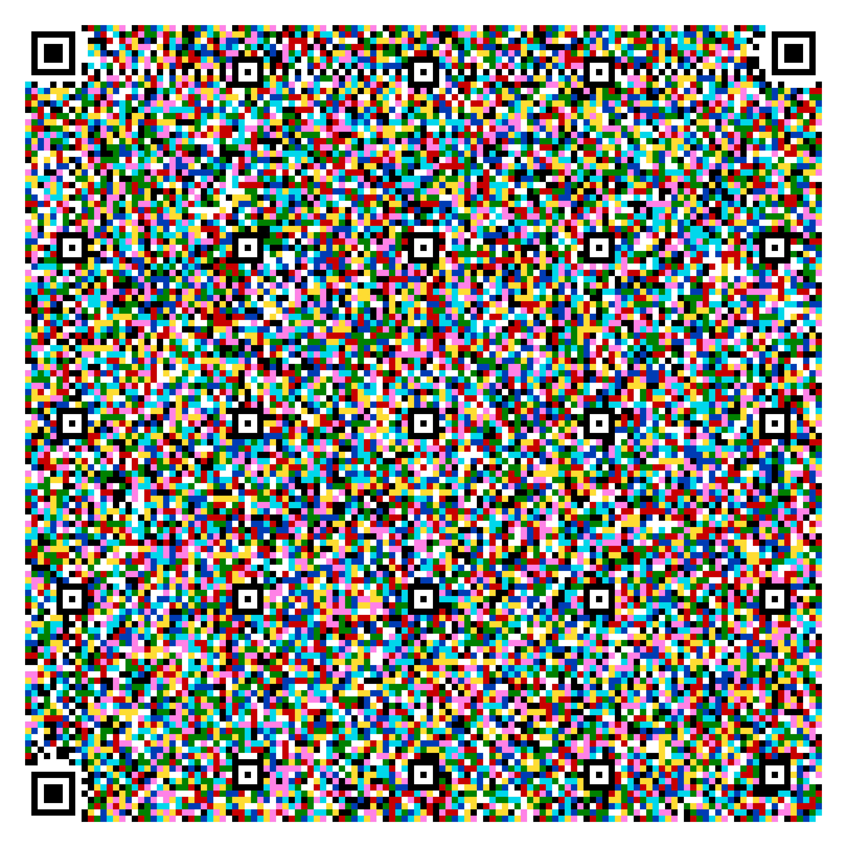
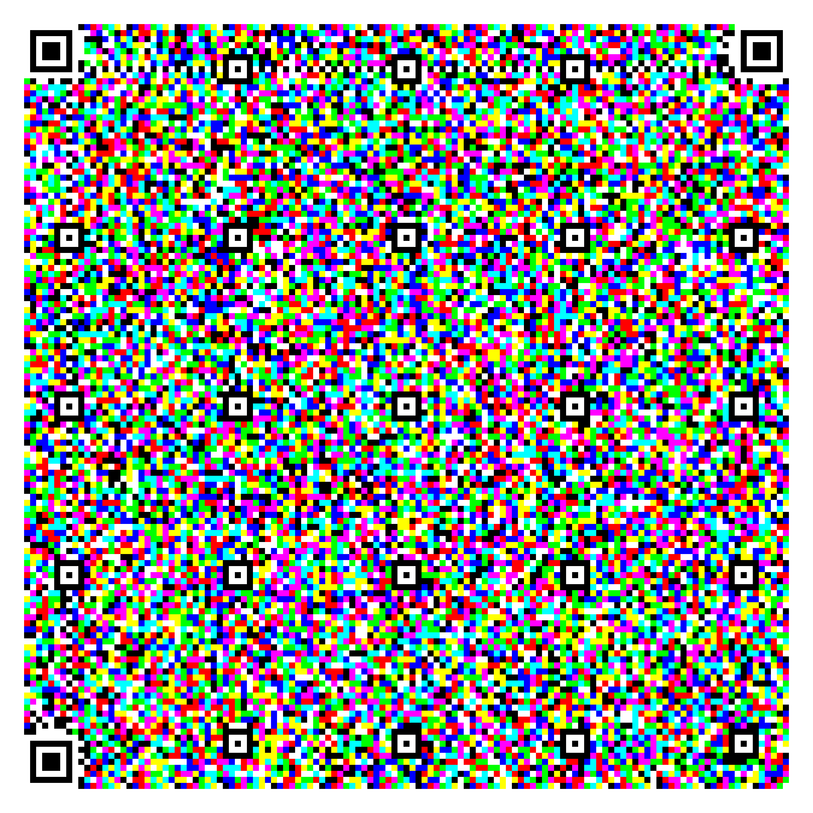
Annex A — Illustrative Examples
The following symbols are HCC2D-compliant barcodes generated according to this specification. Each symbol is scannable with the official HCC2D Decoder app. The figures are rendered at 0.80 mm per module. This corresponds to the physical size on the printed page when the PDF version of this specification is printed at 100% scale on paper.


The following symbols encode Tintern Abbey by William Wordsworth (6,900 bytes, zlib-compressed HCC2DF container), demonstrating HCC2D capacity for long-form text.
— End of Specification —